 少有人走的路
勇哥接触过的基本上是面阵CCD,对于线扫相机没有接触过,这个贴子介绍了线扫相机的halcon标定的知识,放在这里做为扫盲贴子。
一、标定板标定 13.0
在工业镜头选型过程中,为了方便各位朋友计算工业镜头参数,现提供靶面尺寸表供参考。
1.1英寸————靶面尺寸为宽12mm*高12mm,对角线17mm
1英寸————靶面尺寸为宽12.7mm*高9.6mm,对角线16mm
2/3英寸————靶面尺寸为宽8.8mm*高6.6mm,对角线11mm
1/1.6英寸————靶面尺寸为宽8.08mm*高6.01mm,对角线10.07mm
1/1.7英寸————靶面尺寸为宽7.6mm*高5.7mm,对角线9.5mm
1/1.8英寸————靶面尺寸为宽7.2mm*高5.4mm,对角线9mm
1/2英寸————靶面尺寸为宽6.4mm*高4.8mm,对角线8mm
1/3英寸————靶面尺寸为宽4.8mm*高3.6mm,对角线6mm
1/4英寸————靶面尺寸为宽3.2mm*高2.4mm,对角线4mm
1/2.5英寸————靶面尺寸为宽5.76mm*高4.29mm,对角线7.182mm
初始参数的确定*****
针孔摄像机模型为6个参数(Focus,Kappa,Sx,Sy,Cx,Cy)
焦距F = 镜头的标称焦距 【貌似可以随便填】
畸变系数K = 0
Sx = 靶面尺寸宽÷分辨率宽(例如靶面尺寸为1/3 分辨率为1292*964,Sx=4.8÷1292=0.00371mm=3.71e-006m)
标定助手上说是像元的尺寸,但是查到的相机资料像元尺寸又有点不一致,就按照现在的这种方法计算
Sy = 靶面尺寸高÷分辨率高(例如靶面尺寸为1/3 分辨率为1292*964,Sx=3.6÷964=0.00373mm=3.73e-006m)
Sx = 靶面尺寸宽÷分辨率宽(例如靶面尺寸为1/1.7 分辨率为4024*3036,Sx=7.6÷4024=0.00188mm=1.88e-006m)(hk相机MV-CE120-10GC)
Sy = 靶面尺寸高÷分辨率高(例如靶面尺寸为1/1.7 分辨率为4024*3036,Sx=5.7÷3036=0.00188mm=1.88e-006m)
Cx = 分辨率宽÷2
Cy = 分辨率高÷2
原文链接:https://blog.csdn.net/c1learning/article/details/96480168
靶面尺寸:https://blog.csdn.net/maopig/article/details/80773739
* Initialize the program
dev_close_window ()
dev_open_window (0, 0, 768, 576, 'black', WindowHandle)
dev_update_off ()
dev_set_draw ('margin')
dev_set_line_width (3)
set_display_font (WindowHandle, 14, 'mono', 'true', 'false')
*
* Calibrate the camera
*
***6毫米标定板
CalTabDescrFile := 'caltab_6mm.descr'
*****单位是m*****初始参数
gen_cam_par_area_scan_division (0.025, 0, 0.0000037, 0.0000037, 1292/2, 964/2, 1292, 964, StartCamPar)
**gen_cam_par_area_scan_polynomial (0.025, 0, 0, 0, 0, 0, 0.0000037, 0.0000037, 1292/2, 964/2, 1292, 964, StartCamPar)
create_calib_data ('calibration_object', 1, 1, CalibDataID)
set_calib_data_cam_param (CalibDataID, 0, [], StartCamPar)
**set_calib_data_cam_param (CalibDataID, 0, 'area_scan_division', StartCamPar)
set_calib_data_calib_object (CalibDataID, 0, CalTabDescrFile)
NumImages := 10
for I := 1 to NumImages by 1
    read_image (Image, 'E:/Kell/AOI/Calibration/CalibImgs/' + I$'02d')
    get_image_size (Image, Width, Height)
    dev_display (Image)
    Message := 'Find calibration plate in\nall calibration images (' + I + '/' + NumImages + ')'
    disp_message (WindowHandle, Message, 'window', 12, 12, 'black', 'true')
    * Find the calibration plate
    find_calib_object (Image, CalibDataID, 0, 0, I - 1, [], [])
    get_calib_data (CalibDataID, 'camera', 0, 'init_params', StartCamPar)
    get_calib_data_observ_points (CalibDataID, 0, 0, I - 1, Row, Column, Index, Pose)
    get_calib_data_observ_contours (Contours, CalibDataID, 'caltab', 0, 0, I - 1)
    gen_cross_contour_xld (Cross, Row, Column, 6, 0.785398)
    dev_set_color ('green')
    dev_display (Contours)
    dev_set_color ('yellow')
    dev_display (Cross)
    wait_seconds (0.5)
endfor
disp_continue_message (WindowHandle, 'black', 'true')
stop ()
calibrate_cameras (CalibDataID, Error)
get_calib_data (CalibDataID, 'camera', 0, 'params', CamParam)

get_calib_data (CalibDataID, 'calib_obj_pose', [0,1], 'pose', Pose)
**位姿旋转90度
tuple_replace (Pose, 5, Pose[5] + 90, PoseRotate)

***设置标定板厚度 单位是m
set_origin_pose (Pose, 0, 0, 0.0023, PoseNewOrigin)

*选取两个像素点 计算Scale,就是像素精度
ImageRows:=[100,200]
ImageCols:=[100,200]
image_points_to_world_plane (CamParam, PoseNewOrigin, ImageRows, ImageCols, 'm', SX, SY)
distance_pp (ImageRows[0], ImageCols[0], ImageRows[1], ImageCols[1], DistanceImage)
distance_pp (SX[0], SY[0], SX[1], SY[1], DistanceWorld)
*****单位是m*****
*每米世界坐标距离对应的像素点个数
DistanceOneMeter:=DistanceImage/DistanceWorld
*每个像素对应的世界坐标距离
DistanceOnePixel:=DistanceWorld/DistanceImage


**********
**世界坐标系中心偏移量
OffSetX:=(Width/2)*DistanceOnePixel
OffSetY:=(Height/2)*DistanceOnePixel
**设定世界坐标系到图像左上角,不然生成出来的map是从图像中心开始的,map_image只有右下角的部分图像
set_origin_pose (PoseNewOrigin, -OffSetX, -OffSetY, 0, PoseNewOriginFinal)
***********

* Generate map
*Scale的单位是m
gen_image_to_world_plane_map (MapSingle, CamParam, PoseNewOriginFinal, Width, Height, Width, Height, DistanceOnePixel, 'bilinear')
*
* Perform measurements
*
for I := 1 to NumImages by 1
    read_image (Image1, 'E:/Kell/AOI/Calibration/CalibImgs/' + I$'02d')
    **read_image (Image1, 'E:/Kell/AOI/AOI Image2/_01.bmp')
    *
    * Now, measure the size of the black border of the plate
   map_image (Image1, MapSingle, ImageMapped)


   change_radial_distortion_cam_par ('fixed', CamParam, 0, CamParSingleImageRect)
   change_radial_distortion_image (Image1, Image1, ImageRectified, CamParam, CamParSingleImageRect)
endfor


write_image (MapSingle, 'tiff', 0, 'E:/Kell/AOI/Calibration/CalibImgs/ImageMap.tif')
read_image (Image2, 'E:/Kell/AOI/Calibration/CalibImgs/ImageMap.tif')
write_calib_data (CalibDataID, 'E:/Kell/AOI/Calibration/CalibImgs/CalibData.ccd')
read_calib_data ('E:/Kell/AOI/Calibration/CalibImgs/CalibData.ccd', CalibDataID1)


clear_calib_data (CalibDataID)
二、自标定
* This program shows how radial_distortion_self_calibration can be used to
* calibrate the radial distortion coefficient and the center of
* distortions.  In the first part of the program, the edges extracted from
* a single image are used for the calibration.  The results show that the
* radial distortions are extracted fairly accurately from the single
* image.  To increase the accuracy, the second part of the program shows
* how the edges extracted from 20 images can be used to perform the
* calibration.  Since the edges occur in many different orientations in
* the 20 images, the principal point can be determined significantly more
* accurately.
dev_update_off ()
read_image (Image, 'E:/Kell/AOI/Calibration/SelfCalibImgs/c_01.bmp')
dev_close_window ()
dev_open_window_fit_image (Image, 0, 0, -1, -1, WindowHandle)
set_display_font (WindowHandle, 16, 'mono', 'true', 'false')
dev_display (Image)
disp_message (WindowHandle, 'Image with radial distortions', 'window', 0, 0, 'black', 'true')
disp_continue_message (WindowHandle, 'black', 'true')
stop ()
* Extract subpixel-precise edges using the Canny filter.
edges_sub_pix (Image, Edges, 'canny', 1, 10, 30)
union_collinear_contours_xld (Edges, Edges, 10, 1, 2, 0.1, 'attr_keep')
* Segment the edges into lines and circular arcs.
segment_contours_xld (Edges, SplitEdges, 'lines_circles', 5, 4, 2)
* Select edges that are long enough to be useful for the calibration.
select_shape_xld (SplitEdges, SelectedEdges, 'contlength', 'and', 30, 100000)
dev_display (Image)
dev_set_colored (12)
dev_display (SelectedEdges)
disp_message (WindowHandle, 'Extracted edges', 'window', 0, 0, 'black', 'true')
disp_continue_message (WindowHandle, 'black', 'true')
stop ()
dev_clear_window ()
disp_message (WindowHandle, 'Performing self-calibration...', 'window', 0, 0, 'black', 'true')
* Perform the self-calibration of the radial distortions.
radial_distortion_self_calibration (SelectedEdges, CalibrationEdges, 1292, 964, 0.08, 42, 'division', 'variable', 0, CamParSingleImage)
* Rectify the image, i.e., remove the radial distortions.
get_domain (Image, Domain)
change_radial_distortion_cam_par ('fixed', CamParSingleImage, 0, CamParSingleImageRect)
change_radial_distortion_image (Image, Domain, ImageRectified, CamParSingleImage, CamParSingleImageRect)

read_image (Image1, 'E:/Kell/AOI/AOI Image1/_01.bmp')
change_radial_distortion_image (Image1, Domain, ImageRectified1, CamParSingleImageRect, CamParSingleImageRect)

* Display the distorted and undistorted image five times to visualize the
* differences between the images.
dev_display (Image)
dev_display (CalibrationEdges)
disp_message (WindowHandle, 'Edges used for calibration', 'window', 0, 0, 'black', 'true')
disp_continue_message (WindowHandle, 'black', 'true')
stop ()
dev_display (ImageRectified)
disp_message (WindowHandle, 'Image without radial distortions', 'window', 0, 0, 'black', 'true')
disp_continue_message (WindowHandle, 'black', 'true')
stop ()


* Now perform the self-calibration using edges extracted from 20 images.
* The variable Edges will accumulate the edges extracted from the images.
gen_empty_obj (Edges)
for J := 1 to 20 by 1
    read_image (Image, 'E:/Kell/AOI/Calibration/SelfCalibImgs/c_' + J$'02d')
    * Extract subpixel-precise edges using the Canny filter.
    edges_sub_pix (Image, ImageEdges, 'canny', 1, 10, 30)
    union_collinear_contours_xld (ImageEdges, ImageEdges, 10, 1, 2, 0.1, 'attr_keep')
    * Segment the edges into lines and circular arcs.
    segment_contours_xld (ImageEdges, SplitEdges, 'lines_circles', 5, 4, 2)
    * Select edges that are long enough to be useful for the calibration.
    select_shape_xld (SplitEdges, SelectedEdges, 'contlength', 'and', 30, 100000)
    * Accumulate the edges.
    concat_obj (Edges, SelectedEdges, Edges)
    dev_display (Image)
    dev_set_colored (12)
    dev_display (SelectedEdges)
    disp_message (WindowHandle, 'Edges extracted from image ' + J$'d', 'window', 0, 0, 'black', 'true')
endfor
dev_clear_window ()
dev_set_colored (12)
dev_display (Edges)
disp_message (WindowHandle, 'Collected edges from multiple images', 'window', 0, 0, 'black', 'true')
disp_continue_message (WindowHandle, 'black', 'true')
stop ()
dev_clear_window ()
disp_message (WindowHandle, 'Performing self-calibration...', 'window', 0, 0, 'black', 'true')
* Perform the self-calibration of the radial distortions.
radial_distortion_self_calibration (Edges, CalibrationEdges, 1292, 964, 0.08, 42, 'division', 'variable', 0, CamParMultiImage)
dev_clear_window ()
dev_set_colored (12)
dev_display (CalibrationEdges)
disp_message (WindowHandle, 'Edges used for calibration', 'window', 0, 0, 'black', 'true')
disp_continue_message (WindowHandle, 'black', 'true')
stop ()
* Compute the camera parameters of the undistorted image.
change_radial_distortion_cam_par ('fixed', CamParMultiImage, 0, CamParMultiImageRect)
for J := 1 to 20 by 1
    read_image (Image, 'E:/Kell/AOI/Calibration/SelfCalibImgs/c_' + J$'02d')
    get_domain (Image, Domain)
    * Rectify the image, i.e., remove the radial distortions.
    change_radial_distortion_image (Image, Domain, ImageRectified, CamParMultiImage, CamParMultiImageRect)
    * Display the distorted and undistorted image to visualize the
    * differences between the images.
    dev_display (Image)
    disp_message (WindowHandle, 'Image with radial distortions', 'window', 0, 0, 'black', 'true')
    wait_seconds (1)
    dev_display (ImageRectified)
    disp_message (WindowHandle, 'Image without radial distortions', 'window', 0, 0, 'black', 'true')
    wait_seconds (1)
endfor

read_image (Image1, 'E:/Kell/AOI/AOI Image1/_01.bmp')
change_radial_distortion_image (Image1, Domain, ImageRectified1, CamParMultiImage, CamParMultiImageRect)

write_cam_par (CamParMultiImageRect, 'E:/Kell/AOI/Calibration/SelfCalib/CamparRect.dat')
write_cam_par (CamParMultiImage, 'E:/Kell/AOI/Calibration/SelfCalib/Campar.dat')

read_cam_par ('E:/Kell/AOI/Calibration/SelfCalib/Campar.dat', CamParMulti)
三、线阵相机标定
我是使用halcon标定助手来标定线阵相机的,对于里面的一些参数来做一个记录说明:
首先下面的两个数组就是标定之后得到的相机内参和外参
内参:CameraParameters := [0.0357809 , -61.3384 , 6e-006 , 6e-006 , 915.932 , 182.341 , 2048 , 3840 , 1.41028e-006 , 5.45462e-005 , 3.86866e-006]
外参:CameraPose := [-0.0160874,0.0553653,0.255282,28.5899,6.24194,8.48283,0]
内参的11个参数分别是什么意思呢?内参一共十一个参数分别为 [Focus, Kappa, Sx, Sy, Cx, Cy, ImageWidth, ImageHeight, Vx, Vy, Vz]
Focus : 镜头焦距长度
Kappa: 镜头畸变系数,正负分别表示枕形畸变和桶状畸变
Sx: 表示相机单个像元宽度
Sy: 表示相机单个像元高度
Cx: 表示镜头光轴在像平面坐标上的投影横坐标,一般初始化的时候设置为width/2
Cy: 表示镜头光轴在像平面坐标上的投影纵坐标,一般初始化的时候设置为0,因为是一帧是一条线,所以纵坐标为0
ImageWidth: 表示一整副图片像素宽度
ImageHeight: 表示一整幅图片像素高度
Vx : x方向上运动速度,其实就是每拍摄一条线,x方向的走的距离,因为安装有误差,相机和运动方向不可能完全垂直,理论上为0最理想
Vy: y方向上运动速度,其实就是在扫描的时候,多远距离拍摄一条线
Vz: z方向上运动速度,其实就是每拍摄一条线,z方向上走的距离,也是因为安装有误差,理论上为0最理想
外参的六个参数表示由世界坐标系转换成相机坐标系的变换参数,六个参数分别为x,y,z三个轴的旋转角度和x,y,x三个轴的平移量
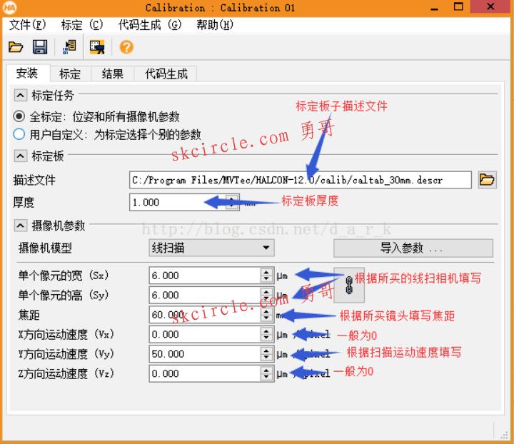
在halcon中使用标定助手对线扫相机进行标定,首先设置标定板描述文件路径,和镜头等相关参数
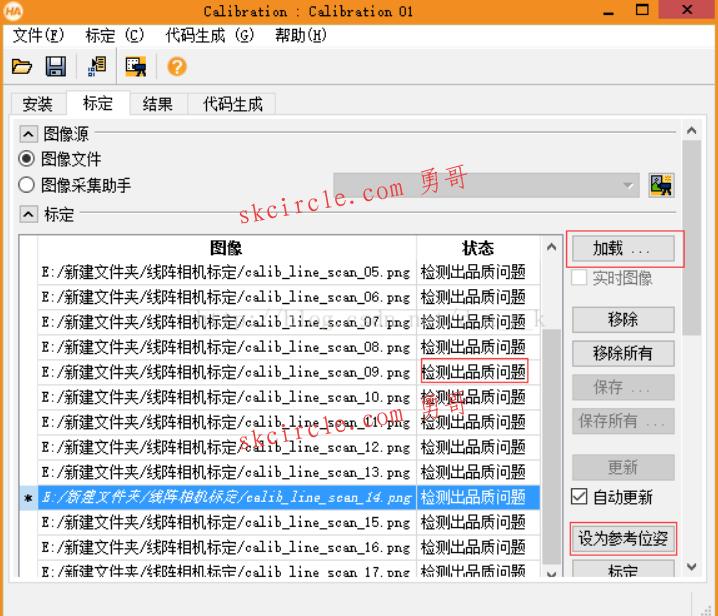
2.加载用于标定的图片,一般20张左右,注意加载的图片必须都找到标定板,显示检测品质出问题如果精度要求不是很高也可以接受。然后选定一张照片设置为参考位姿,设置参考位姿的作用是什么呢?当你标定完成之后,使用相机内参外参进行矫正之后的图片,会将这个图片上的标定板中心点作为远点坐标,并且这张变换后的图片作为相机垂直照射的平面参考。如果加载的图片找不到标定板,可以在最下方的标定板提取参数中改变参数,一般就能找提取到标定板了。最后点击标定按钮,就可以得到标定的参数了。
3.得到的内参,如何进行畸变矫正呢?
你希望映射过后的图片的宽度(一条线)内视野为多少,这里为30mm,然后除以1000换算成m
TmpCtrl_RectificationWidth := 30
TmpCtrl_RectificationWidth := TmpCtrl_RectificationWidth / 1000.0
生成用于矫正的映射图,着重说一下这几个输入参数
CameraParameters:标定得到的相机内参
CameraPose:标定得到的相机位姿外参
2048:待转换图的宽度
3840:待转换图的高度
2048:转换之后的图像希望的宽度
3840:转换之后的图像希望的高度
TmpCtrl_RectificationWidth / 2048:表示希望转换后的图,每个像素代表的长度,单位是m。这里因为宽度视野(一条线覆盖的视野宽度)希望是30mm,而希望转换后的图像宽度为2048,所以这里用TmpCtrl_RectificationWidth / 2048,也就是说你可以自定义转换之后的图像每隔像素代表多少精度,这里的精度就是30mm/2048pix = 0.014mm/pix .注意下面的这个函数就是将图片转换成了z=0,垂直视角的函数,参看halcon函数说明。
gen_image_to_world_plane_map (TmpObj_RectificationMap, CameraParameters, CameraPose, 2048, 3840, 2048, 3840, TmpCtrl_RectificationWidth / 2048, 'bilinear')
最终使用map_image来转换图片,转换之后的图片在理论上横向纵向的坐标缩放比例是相等的,换句话来说一个正方形两个方向上的像素个数是一样的,并且是垂直拍摄的。
map_image (Image, TmpObj_RectificationMap, TmpObj_RectifiedImage)
如何制作标定板
https://blog.csdn.net/mvtechnology/article/details/9388219
————————————————
版权声明:本文为CSDN博主「c1learning」的原创文章,遵循 CC 4.0 BY-SA 版权协议,转载请附上原文出处链接及本声明。
原文链接:https://blog.csdn.net/c1learning/article/details/99948274


")
")
常用的6种方法")
 封装运动功能")
")


")